OLED display
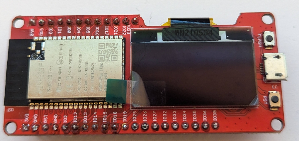
The SSD1306 OLED display is a cheap and popular display. It is, for example, the display that is used on the Makerfabs ESP32 board.
In this tutorial we will write text on it, and draw some icons.
Prerequisites
This tutorial assumes that you have done the i2c tutorial.
We recommend to have read the packages tutorial, since we are going to use a package for the SSD1306 driver.
Setup
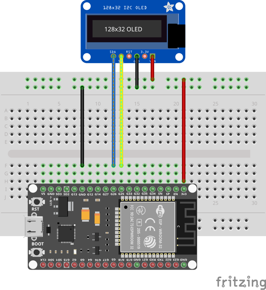
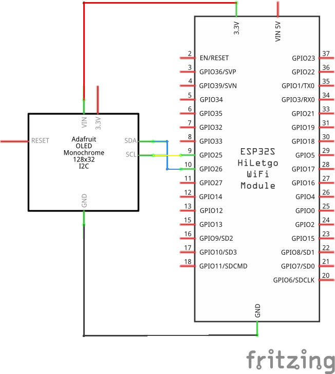
Connect the display to the ESP32 board as follows:
- VCC/VIN to 3V3
- GND to GND
- SCL to pin 25
- SDA to pin 26
Many boards that have an SSD1306 display integrated (like the Makerfabs MaESP Oled or the Wemos Lolin) have the display connected to pins 4 (SDA) and 5 (SCL). If you use one of these boards you have to change the code below to use these pins.
The Heltec boards with integrated displays, use the following pins:
- v2: SDA=4, SCL=15
- v3: SDA=17, SCL=18
Note that we use the Adafruit 128x32 display in the following diagrams. The connections are the same for 128x64 displays.
Packages
The driver for the SSD1306 is not part of the standard Toit distribution, but must be downloaded as package. See the packages tutorial for details.
We are using the ssd1306 package. To install it, run the following command in your project directory:
You can probably just write jag pkg install ssd1306, but the full ID together
with the version is more explicit, and will make sure you get the right package.
Similarly, install the pixel-display package to provide convenience methods to draw on the display:
For information about how to use the display libraries, see the display documentation.
In this tutorial, we are just going to show a few examples.
Text
Start a ssd1306_text.toit program and watch it with Jaguar.
Enter the following program:
import font show *
import gpio
import i2c
import pixel-display show *
import pixel-display.two-color show *
import ssd1306 show *

current-date:
  now := Time.now.local
  return "$now.year-$(%02d now.month)-$(%02d now.day)"

current-time:
  now := Time.now.local
  return "$(%02d now.h):$(%02d now.m):$(%02d now.s)"

main:
  sda := gpio.Pin 26
  scl := gpio.Pin 25
  frequency := 400_000

  bus := i2c.Bus --sda=sda --scl=scl --frequency=frequency

  devices := bus.scan
  if not devices.contains Ssd1306.I2C-ADDRESS:
    throw "No SSD1306 display found"

  device := bus.device Ssd1306.I2C-ADDRESS
  driver := Ssd1306.i2c device
  display := PixelDisplay.two-color driver
  display.background = BLACK

  sans := Font.get "sans10"
  [
    Label --x=30 --y=20 --text="Toit",
    Label --x=30 --y=40 --id="date",
    Label --x=30 --y=60 --id="time",
  ].do: display.add it

  STYLE ::= Style
      --type-map={
          "label": Style --font=sans --color=WHITE,
      }
  display.set-styles [STYLE]

  date/Label := display.get-element-by-id "date"
  time/Label := display.get-element-by-id "time"
  while true:
    date.text = current-date
    time.text = current-time
    display.draw
    sleep --ms=250
As a first step we create an i2c
bus object with:
i2c.Bus --sda=sda --scl=scl --frequency=frequency.
This calls the constructor of the Bus
class, passing in the named arguments.
The display supports the "fast" mode of i2c which is why we can set the
frequency to 400KHz (and not just 100KHz). The code would work the
same way with 100KHz. Usually, 700kHz works too, and makes for slightly
faster updates.
We then instantiate an Ssd1306 object by calling its i2c constructor.
As argument it receives the i2c device with ID Ssd1306.I2C-ADDRESS.
The value of Ssd1306.I2C-ADDRESS is equal to 60, thus
identifying the display on the bus.
With the driver object we can then build a display object which gives us some useful methods to operate the display. We can set the background color to BLACK, and then use the WHITE constant to write later.
Writing text is done by adding Label elements to the display, then styling them with a Style object. The style object sets the font and color for the Label elements.
Note that operations on the display don't immediately interact
with the physical display but build up a drawing queue/graph instead.
Only with display.draw is the content constructed and sent to the
physical display.
This has two major advantages. We can reuse the graph and simply
update the parts that change. In our example we have a while-true
loop that just updates the objects we received from the get-element-by-id
calls. We could also call move-to on the object to move it
somewhere.
The program writes 3 lines:
Toit,- the date in ISO 8601 format, and
- the time.
Time
By default the device starts with a time set to 1970. You can use the ntp package to synchronize the device's time.
See this example.
Icons
As the name implies, it is possible to draw individual pixels onto a display. However, in many cases, icons are completely sufficient.
Toit provides a package with icons from the Pictogrammers project. To use them, install the pictogrammers_icons:
Start a new file and save it as display_icon.toit. Use jag watch to
run it whenever it is saved.
Enter the following code into the new file:
import pictogrammers-icons.size-48 as icons
import gpio
import i2c
import pixel-display show *
import pixel-display.two-color show *
import ssd1306 show *

get-display -> PixelDisplay:
  sda := gpio.Pin 26
  scl := gpio.Pin 25
  frequency := 400_000

  bus := i2c.Bus --sda=sda --scl=scl --frequency=frequency

  devices := bus.scan
  if not devices.contains Ssd1306.I2C-ADDRESS:
    throw "No SSD1306 display found"

  device := bus.device Ssd1306.I2C-ADDRESS
  driver := Ssd1306.i2c device
  return PixelDisplay.two-color driver

main:
  display := get-display
  display.background = BLACK

  icon := Label --x=0 --y=50 --icon=icons.HUMAN-SCOOTER --color=WHITE
  display.add icon
  while true:
    80.repeat:
      icon.move-to it 50
      display.draw
      sleep --ms=1
    sleep --ms=2_000
The code starts again by creating the display. This time we moved
the display-creation code into its own function
(get-display which returns a PixelDisplay).
If your display is only a 32-line display you need to add the
argument --height=32 to the driver creation. In some cases
you also need to play with the following arguments:
--flip, to flip the display vertically,--inverse, to invert black and white,--layout=XXXwhereXXXis one ofLAYOUT-SEQUENTIAL,LAYOUT-SEQUENTIAL-SWITCHED,LAYOUT-ALTERNATED, orLAYOUT-ALTERNATED-SWITCHED.
For this simple example, we don't create a style object. We just
pass the color to the constructor of the Label.
We then add the icon-label to the display and start a loop. For each iteration, the position is updated before every draw. This makes the icon move from left to right over the display.
You can browse the icons at: https://materialdesignicons.com/.
Often, devices are used for temperature measurements, in which
case icons that start with icons.WEATHER_ are interesting. Use
the completion to see which icons exist.
Exercises
As long as the connections were done correctly you can't damage your hardware by changing your program.
- Change the text.
- Fix the device's internal time before showing anything on the display. See the ntp package and the corresponding example.
- Invert the colors, so that the background is white and the text is black.