LED
In this tutorial we will control a single LED from a Toit program.
Prerequisites
We assume that you have set up your development environment as described in the IDE tutorial.
We also assume that you have flashed your device with Jaguar and that you are familiar with running Toit programs on it. If not, have a look at the Hello world tutorial.
Setup
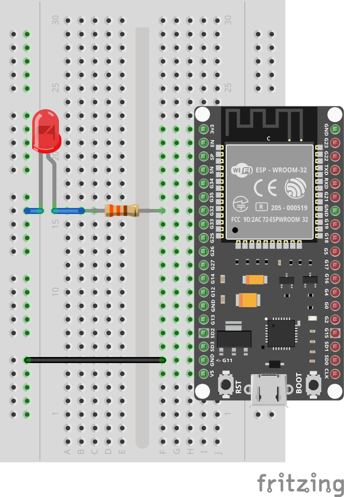
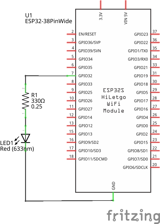
Connect the LED and the 330Ω resistor so that they are in series between pin 32 and GND.
LEDs have a direction. The longer leg must point to the pin (the positive side).
Current limiting resistor
An LED always needs a current-limiting resistor to avoid damaging the microcontroller.
Ignoring the LED (which will reduce the current even further) we can compute the maximum current that flows through the resistor as follows:
The maximum voltage an ESP32 pin can produce is 3.3V and the resistor is 330Ω.
Ohm's law,
V=R*I, gives us an upper limit of how much current the ESP32 will have to provide on its pin 32.Plugging in the numbers we get
3.3=330*I, thus yieldingI=3.3/330=10mA.
According to the datasheet, an ESP32 can handle up to 12mA, and this setup is thus safe.
Code
It's time to write a program that controls the LED.
Open a new file and enter the following code:
Save it as led1.toit and run the program.
The LED should light up for 1 second and then go dark again.
We can improve this program by running inside a loop:
import gpio

main:
  pin := gpio.Pin 32 --output
  while true:
    pin.set 0
    sleep --ms=500
    pin.set 1
    sleep --ms=500
The program is now running in an infinite loop. It will not stop on its own anymore. (This is also the reason we can remove the pin.close).
Exercises
As long as the connections were done correctly you can't damage your hardware by changing your program. If you change the connections, make sure that the LED is always in series with a resistor.
Experiment as much as you want.
For example:
- Change the speed of the blinking.
- Add more lines so that the program emits an SOS signal
- Connect the resistor to 3V3 instead of GND, and change the direction of the LED. Now the LED turns on when the pin is set to 0 and not 1.