Button
In this tutorial we will use a button as input to the ESP32.
Prerequisites
We assume that you have set up your development environment as described in the IDE tutorial.
We also assume that you have flashed your device with Jaguar and that you are familiar with running Toit programs on it. If not, have a look at the Hello world tutorial.
While not strictly necessary, we recommend that you have completed the LED tutorial before starting this one.
Hardware
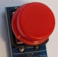
This tutorial works with any button that can connect two pins when pressed.
If you have a button with 3 pins, typically with an integrated pull-down resistor, then you can just use two pins ("VCC" and "OUT").
Setup
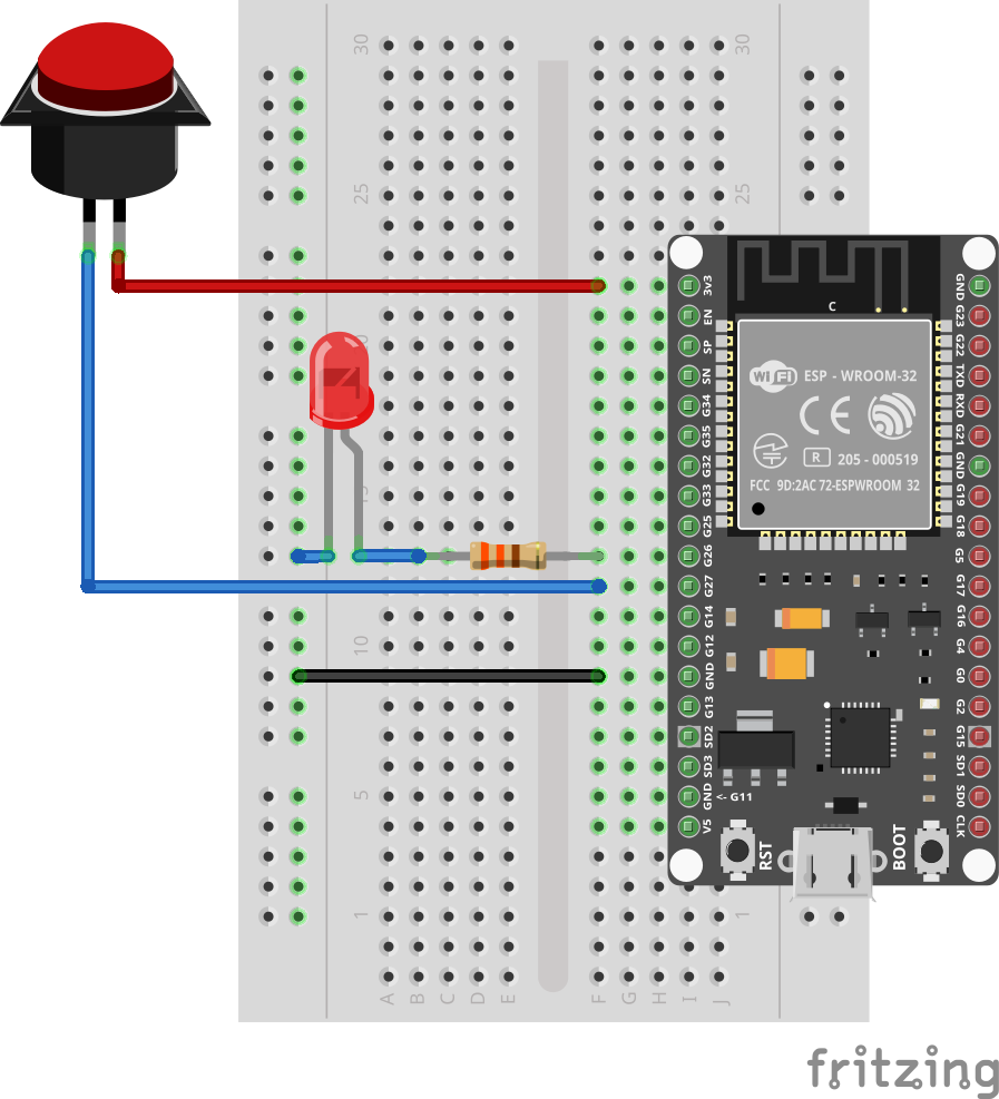
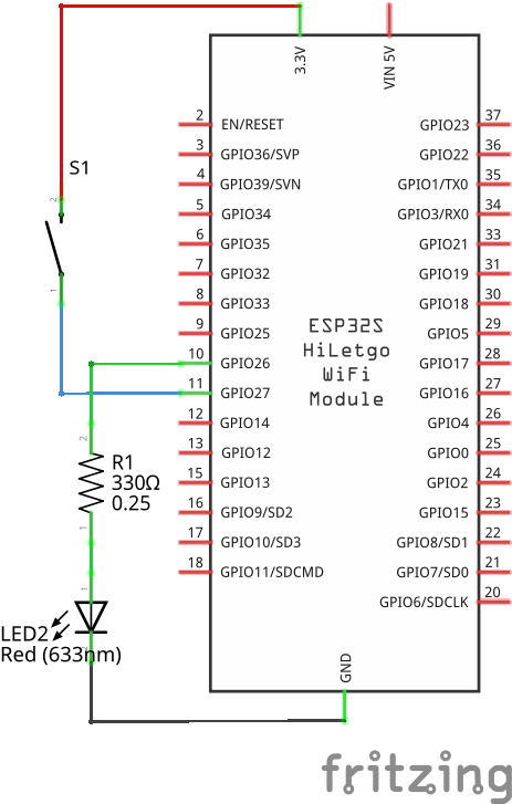
Connect the LED and the 330Ω resistor so that they are in series between pin 26 and GND. See the LED and LEDs tutorials for more details.
Connect the board's 3V3 pin to one of the pins of the button, and connect the other pin of the button to pin 27.
If you have a three-pin button, then connect the button's VCC pin to 3V3, and its OUT to pin 27.
LEDs have a direction. The longer leg must point to the pin (the positive side).
Code
Create a new file button.toit and start jag watch button.toit to run
the program whenever you save.
import gpio

main:
  button := gpio.Pin 27 --input --pull-down
  led := gpio.Pin 26 --output

  while true:
    if button.get == 1:
      led.set 1
    else:
      led.set 0
After initializing the button and led variables, the code starts an
infinite loop. Whenever it detects that the button is pressed
(button.get == 1) it sets the LED pin to 1, thus turning it on.
Otherwise it sets it to 0, turning it off.
A shorter variant of this program avoids the if:
import gpio

main:
  button := gpio.Pin 27 --input --pull-down
  led := gpio.Pin 26 --output

  while true:
    led.set button.get
In the loop the LED is simply set to the value of the button.
Waiting
Instead of continuously polling the input pin, we can also wait for the
button to be pressed. This is done using the wait-for method:
import gpio

main:
  button := gpio.Pin 27 --input --pull-down
  led := gpio.Pin 26 --output

  while true:
    button.wait-for 1
    led.set 1
    button.wait-for 0
    led.set 0
While the program is stopped at the wait-for call, it does not use any
CPU time. Other processes or tasks can run in the
meantime.
It's generally a good idea to use wait-for instead of polling.
Integrated pull-down resistor
Some buttons have an integrated pull-down resistor. In this case you
could connect the board's GND to the button's GND pin, and remove the
--pull-down from the code.
We generally recommend to stick with the internal pull-down resistor, as you are less likely to accidentally create a short-circuit.
Exercises
When the button is pressed, it connects directly to VCC. If the button's OUT pin is connected to an ESP32 pin that is configured as output, then the ESP32 could get damaged.
Always make sure that the button's OUT pin is connected to an ESP32 pin that is configured as input.
For additional safety one could add a 330Ω resistor between the button's OUT pin and the ESP32.
- Turn the LED off when the button is pressed instead of the opposite.
- Blink 3 times when the button is pressed.
- Connect the button's second pin to GND instead of 3V3, and use a pull-up resistor instead of a pull-down resistor.