ADC
An analog-to-digital converter (ADC) makes it possible to measure the voltage at a certain pin. The ESP32 features two 12-bit SAR (Successive Approximation Register) ADCs, supporting a total of 18 measurement channels (analog enabled pins). However, the usage of ADC2 is severely restricted and is therefore disabled by default. In general you should use pins 32-39 (8 pins) for ADC conversion as they don't interfere with the WiFi radio.
Prerequisites
We assume that you have set up your development environment as described in the IDE tutorial.
We also assume that you have flashed your device with Jaguar and that you are familiar with running Toit programs on it. If not, have a look at the Hello world tutorial.
While not necessary, we recommend to have done the digital GPIO tutorials LED and Button before this one.
Setup
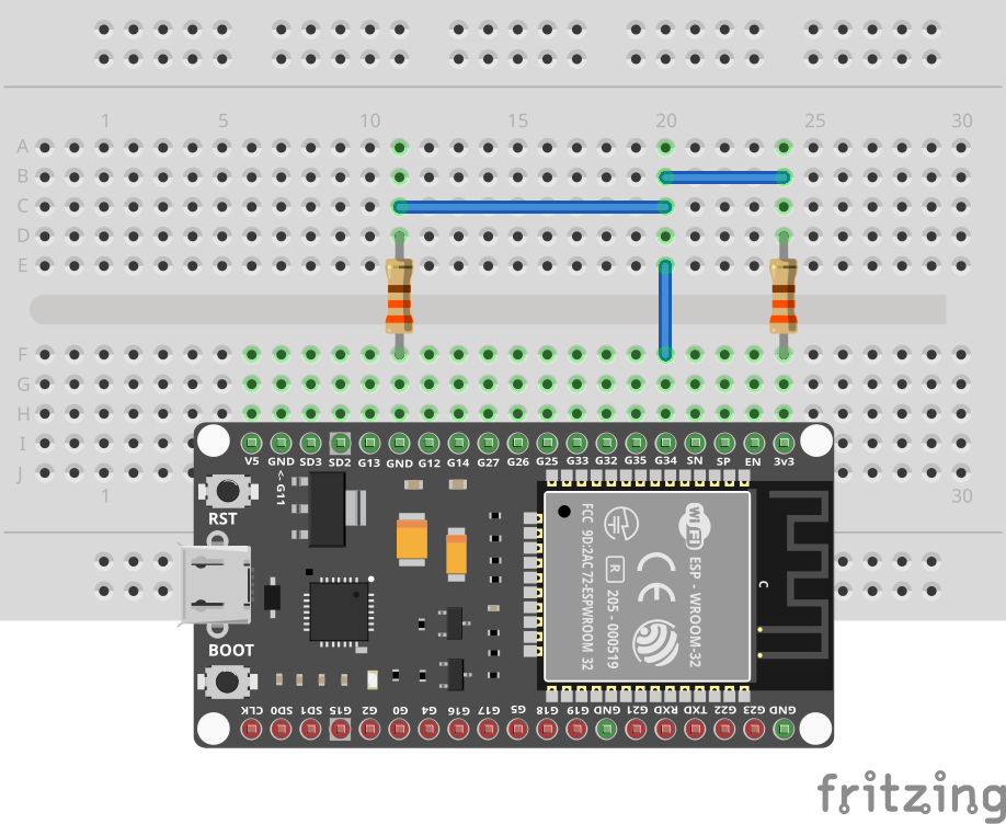
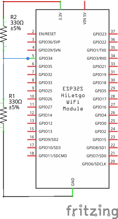
We are using pin 34 for this tutorial. Pin 34 is input only, which works well for the ADC.
Our first setup implements a typical voltage divider. We connect a resistor to 3V3, and another resistor to GND. The two resistors are connected in series. The voltage between the two resistors is measured by the ADC.
Note that we use 330Ω resistors. This is a very low value, but it is likely that you have these resistors in your kit. If you have higher value resistors, you can use them instead. The higher the resistance, the lower the current, and the less power is wasted as heat.
Code
A voltage divider is a simple circuit that divides the voltage using two resistors. If you have two resistors of the same value, the voltage between the two resistors will be half of the voltage between the end of the first resistor and the end of the second resistor. In our case the voltage between the two resistors should be 1.65V.
Let's test this. Write (and Jaguar-watch) the following program:
import gpio
import gpio.adc

main:
  pin := gpio.Pin 34
  adc := adc.Adc pin
  256.repeat:
    print adc.get
    sleep --ms=500
This program should output 1.65V in a loop.
You can shorten the output by using print "$(%1.3f adc.get)". This
uses Toit's string interpolation
to print the value with 3 digits.
VCC or GND
Before using the ADC for other projects, it's often a good idea to make sure that everything is still working. In that case, using VCC or GND as a test input is a good idea. The voltage of VCC is 3.3V, and the voltage of GND is 0V. The ADC should be able to measure these values.
Since the pin 34 is configured as input, it is safe to connect it directly to VCC or GND. However, you can also keep a resistor in between. That shouldn't change the measured value, but prevents accidentally shorting the pin to VCC or GND (if it isn't input as expected).
While the loop is running (restart it if necessary), remove the resistor that connects pin 34 to GND. The value should immediately rise to a value close ~3.3V. Exactly, what we expected.
Reconnect the resistor and remove the cable that connects the resistor of 3V3 to pin 34. On my hardware the value immediately drops to ~0.142V.
This is somewhat surprising because GND should be 0V. According to Espressif's specification, the ADC has a precision of 12 bits (thus 4096 values) and ~0.14V is thus not just an imprecision.
It turns out that the ADC is non-linear and can't really measure very low and high values: https://docs.espressif.com/projects/esp-idf/en/v4.2/esp32/api-reference/peripherals/adc.html#adc-calibration
Keep this in mind when using the ADC.
Exercises
In order not to damage the hardware:
- Make sure not to measure directly the 5V pin. You can measure it's voltage using a voltage divider.
- Don't connect GND and 3V3/5V.
- Keep pin 34 pin as input.
LED voltage drop
Measure the voltage drop of an LED. Replace the resistor that connects pin 34 to GND with an LED. (You should have VCC -> resistor -> pin 34 -> LED -> GND). Remember that the short leg of the LED is the cathode (negative side) and should be connected to GND.
Typical voltage drops of red/green LEDs are between 1.6V and 2.2V. As such you should measure a value in the range of 1.1V (3.3 - 2.2) to 1.7V (3.3 - 1.6).